

This guide covers installation for Stinger, Stinger PRO, and Stinger PRO Hideaway lightheads. Mounting is similar across products, but wiring and control logic differ. Review your product type before starting.
Identify Your Stinger Type
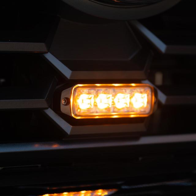
- – Stinger PRO (Surface Mount)
Uses +12V trigger wires for color and pattern control - – Standard Stinger (Surface Mount)
Uses a single +12V power wire with ground-trigger control for color and pattern changes - – Stinger PRO Hideaway (Surface Mount)
Uses +12V pattern mode wires with ground-trigger pattern control and built-in priority override logic
Tools and Materials Needed
- – Drill and drill bits (if mounting requires it)
- – Screwdriver or nut driver
- – Wire strippers and crimpers
- – Heat shrink or weatherproof connectors
- – Fuse tap or inline fuse holder
- – Electrical tape or wire loom
- – Switch panel or toggle switches
- – Multimeter (recommended)
Mounting the Lightheads
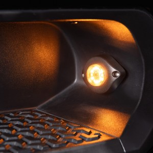
Surface Mount (Stinger and Stinger PRO)
- – Choose a flat mounting location such as grille, bumper, headache rack, or rear surface
- – Clean and dry the mounting area thoroughly
- – Test fit the lighthead before drilling
- – Place the foam gasket behind the light
- – Secure using supplied self-tapping screws
- – Ensure the light is level and properly oriented
| Product | Overall Dimensions (W x H x D) | Mount Hole Spacing |
| Stinger | 4.1″ x 1.0″ x 0.3″ | 4.0″ |
| Stinger PRO 4 | 4.0″ x 1.12″ x 0.57″ | 3.7″ |
| Stinger PRO 12 | 5.0″ x 1.87″ x 0.53″ | 4.56″ |
| Stinger PRO Hideaway | 2.42″ x 2.0″ x 1.87″ | 2.0″ |
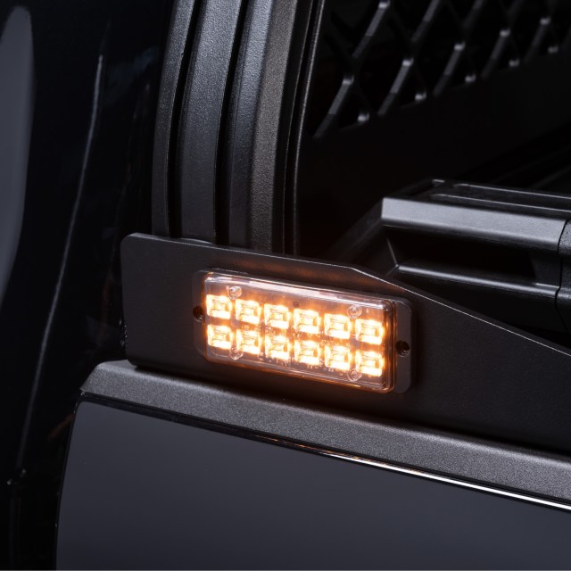
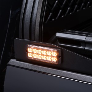
Stinger PRO Hideaway Installation
- – This Hideaway model is a self-contained lighthead and does not install inside factory headlights or taillights
- – Do not drill into OEM light housings
- – Choose an exterior mounting location such as grille, rocker panel, running boards, rack, or utility – body
- – Clean and dry the mounting surface
- – Test fit the unit before securing
- – Use supplied bolts and hardware with the included gasket
- – Ensure proper orientation and visibility before final tightening
Wiring Overview
All Stinger lightheads require:
- – A clean +12V power source (fuse tap recommended)
- – A solid chassis ground
Control wiring differs by product. Please do not assume all Stinger lights wire the same.
Stinger PRO Wiring (Positive Trigger System)
- – Black = Ground
- – Orange = +12V (Amber)
- – Gray = +12V (White)
- – Blue = +12V (Blue, if equipped)
- – Yellow = Pattern change (tap to +12V)
- – White = Troubleshoot wire (do not use)
How it works:
- – Apply +12V to the color wire you want active
- – Tap the yellow wire to +12V to cycle patterns
- – The light will remember the last pattern used
Standard Stinger Wiring (Ground Trigger System)
- – Red = +12V power
- – Black = Ground
- – White = Color change (tap to ground)
- – Yellow = Pattern change (tap to ground)
- – Blue = Troubleshoot wire (do not use)
How it works:
- – Light powers on with Red and Black connected
- – Tap White to ground to change color
- – Tap Yellow to ground to change pattern and speed
- – The light will remember the last pattern used
Important:
- – These control wires must go to ground, not +12V
- – This wiring logic is different from Stinger PRO
Stinger PRO Hideaway Wiring (Mode-Based System)
- – Black = Ground
- – Red = Pattern Mode 1 (+12V)
- – White = Pattern Mode 2 (+12V)
- – Yellow = Pattern Mode 3 (+12V)
- – Blue = Pattern change (tap to ground)
- – White (second) = Troubleshoot wire (do not use)
How it works:
- – Apply +12V to one mode wire (Red, White, or Yellow) to activate that mode
- – Only one mode wire should be powered at a time
- – If multiple are powered, the highest priority will override:
- – Mode 3 overrides Mode 2 and Mode 1
- – Mode 2 overrides Mode 1
- – With a mode active, tap the blue wire to ground to change patterns
- – The selected pattern is saved to that specific mode
Wiring Multiple Lights (Sync and Setup)
Syncing Lights
- – Stinger PRO: connect all yellow wires together and tap to +12V
- – Standard Stinger: connect all yellow wires together and tap to ground
- – Hideaway: tap blue wires to ground until all units match
Common Setup Examples
- – Front grille: 2 or 4 lights wired together for synchronized output
- – Rear setup: multiple lights across bumper or rack
- – Left and right pairing: install in symmetrical positions for balanced visibility
Zoning
- – Use separate switches for front and rear zones if independent control is needed
- – Plan wiring layout before installation
Power and Circuit Planning
- – Use a fuse tap or dedicated fused circuit
- – Run an appropriate fuse based on total load
- – Keep wiring organized using loom or zip ties
- – Avoid routing wires near heat or moving components
Pro Tips
- – Test all functions before final mounting
- – Use a common ground point for multiple lights
- – Label wires when installing multiple units
- – Plan switch layout before wiring
- – Keep installs symmetrical for a clean, professional look
- – Use dielectric grease on connections for durability (apply a thin layer on connector or housing, not directly between metal contact surfaces).
Troubleshooting
- – Light does not turn on
Check power and ground connections - – Pattern will not change
Verify correct trigger type (ground vs +12V) - – Color not changing
Confirm correct control wire and trigger type - – Lights not syncing
Ensure sync wires are connected and using correct trigger method - – Intermittent operation
Check for loose connections or poor grounding
Final Notes
- – Stinger PRO and Standard Stinger use different control logic and should not be wired the same
- – Stinger PRO Hideaway is designed for external mounting and is not installed inside factory light housings
- – Always verify wiring before applying power
- – Check local regulations before using warning lights on public roads
See It For Yourself!


Explore More Stinger Guides
- – New Product: Stinger Grille Brackets
- – New Product: Stinger Chase Light Kit
- – LED Stinger Lights FAQ
- – Where to Install LED Strobe Lights on a Truck
- – How Many Strobe Lights Do You Need?
Recommended Products
Putco Stinger™ PRO LED Strobe Lightheads
From: $106.99

Putco Stinger™ PRO Hideaway Amber LED Strobe Lights
From: $80.99